Intro to Emissions
What is an emissions control system
Emission control systems are regulated by the EPA and CARB
- Emission control system is a unique group of emission control devices, auxiliary emission control devices, engine modifications and strategies, and other elements of design designated by the Administrator used to control exhaust emissions of a vehicle.
- Catalytic converters: Three-Way Catalyst (TWC), Diesel Oxidation Catalyst (DOC),
Selective Catalytic Reduction (SCR) system including Diesel Exhaust Fluid (DEF) tank and injector - EGR system, Diesel Particulate Filter (DPF) system, Positive Crankcase Ventilation (PCV) system, Evaporative Canister
- Base Engine components: air induction system; intake manifold; camshaft; combustion chamber; fuel injectors; exhaust manifold
- Catalytic converters: Three-Way Catalyst (TWC), Diesel Oxidation Catalyst (DOC),
- Element of design means any control system (i.e., computer software, electronic control system, emission control system, computer logic), and/or control system calibrations, and/or the results of systems interaction, and/ or hardware items on a motor vehicle or motor vehicle engine.
- Electronic Control Unit (ECU, ECM, TCM, …) and associated control and diagnostic strategies, ECU software, and ECU calibration files*
- Intake Air and/or Exhaust Temperature / Pressure / Flow Sensors; Exhaust Oxygen Sensors*
- On-Board Diagnostic (OBD) system
- Auxiliary Emission Control Device (AECD) means any element of design which senses temperature, vehicle speed, engine RPM, transmission gear, manifold vacuum, or any other parameter for the purpose of activating, modulating, delaying, or deactivating the operation of any part of the emission control system.
- Any part of the engine or emission control system – hardware or ECU – which senses any parameter for the purpose of controlling any part of the emission control system
*Dynojet Products
Emissions System Overview
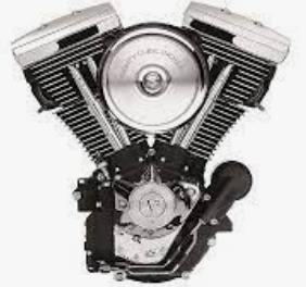
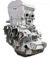
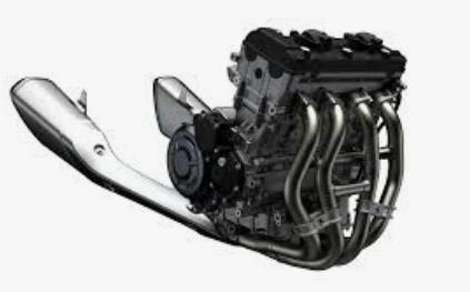
Internal Combustion Engines (ICE)
- The combustion process creates harmful byproducts like carbon monoxide (CO), unburned hydrocarbons (HC), oxides of nitrogen (NOx), and fine particulate matter (PM) which are released to the air as we drive.
- Emissions pollutants can cause respiratory disease, premature death, and environmental harm.
- Maintaining a properly functioning emissions control system reduces these pollutants which harm both humans and the environment.
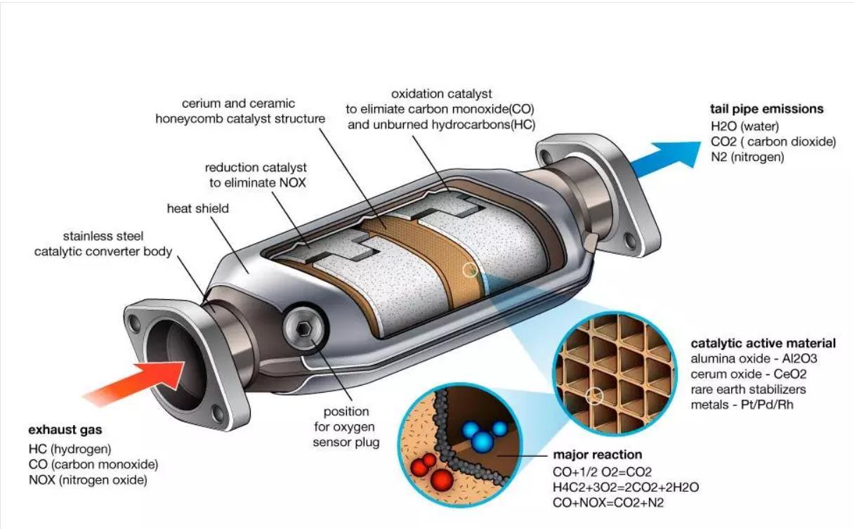
Catalytic Converters
- CATs are installed in the exhaust system and are probably the most important aspect of an emissions reduction system in modern vehicles.
- Exhaust gases entering the Catalytic Converter include products of incomplete combustion (such as CO, HC, NOx, and PM) which are harmful to our health and the environment.
- Inside the CAT, a series of different elements act as catalyst to promote the chemical reactions to eliminate the dangerous gases as they pass through the CAT.
- Effectiveness of three-way catalytic converters depend on the Air:Fuel ratio of the incoming exhaust gas.
- Air:Fuel ratio is controlled by the ECU using feedback from the Exhaust Gas Oxygen sensors
- In the first stage, the gases encounter a filter-type element with tiny honeycomb-like passages. The “filter” substrate is made of ceramic and is coated with “precious metals” (Rhodium, Platinum and/or Palladium).
- The catalyst is very hot, and as these compounds pass through the first element, the Nitrogen molecules are the first to react. The CAT, causes the NOx element to break apart, forming Nitrogen (N2) and Oxygen (O2).
- The gas flows into the second ceramic block where it reacts with Platinum and Palladium. Here the Crbon Monoxide (CO) bonds with the free Oxygen (O2) forming Carbon Dioxide (CO2).
- The unburned Hydrocarbons (HC) also react with the Oxygen (O2) to form water (H2O) and Carbon Dioxide (CO2)
- This exhaust gas now exits the vehicle being less toxic, containing primarily Carbon Dioxide (CO2), Nitrogen (N2), and Water Vapors (H2O) and very low levels of harmful emissions.
EGR – Exhaust Gas Recirculation
- EGR is also used to control emissions by reducing the amount of NOx produced by the engine.
- EGR recirculates a portion of the spent exhaust gases back into the combustion chamber.
- This displaces some of the available O2 entering the engine and provides gases that are inert to combustion to act as absorbents of combustion heat.
- This reduces combustion chamber temperatures, which also reduces the amount of NOx generated in the engine.
- Another benefit of EGR in spark-ignited engines is an increase in efficiency. EGR reduces pumping losses, so the engine doesn’t have to work as hard.
- EGR systems are most active during light- to moderate- acceleration and cruising situations.
- Idle and WOT generally do not see much EGR if any:
too much EGR in these operating conditions can cause unstable combustion and misfires
- Idle and WOT generally do not see much EGR if any:
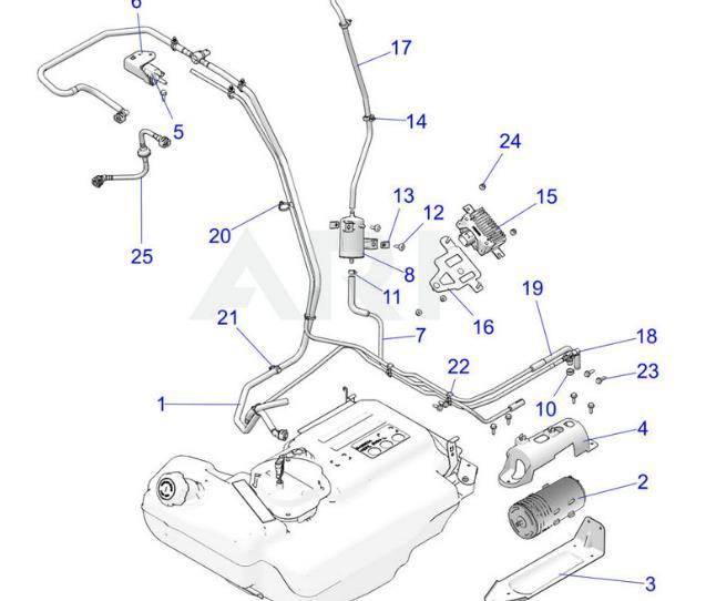
EVAP – Evaporative Emission Control Systems
- Evaporative emissions are another type of emission from gasoline vehicles. The gasoline in your tank and fuel lines evaporate, releasing hydrocarbon vapor, also called “volatile organic compounds”.
- EVAP systems are designed to store and dispose of fuel vapors before they can escape into the atmosphere.
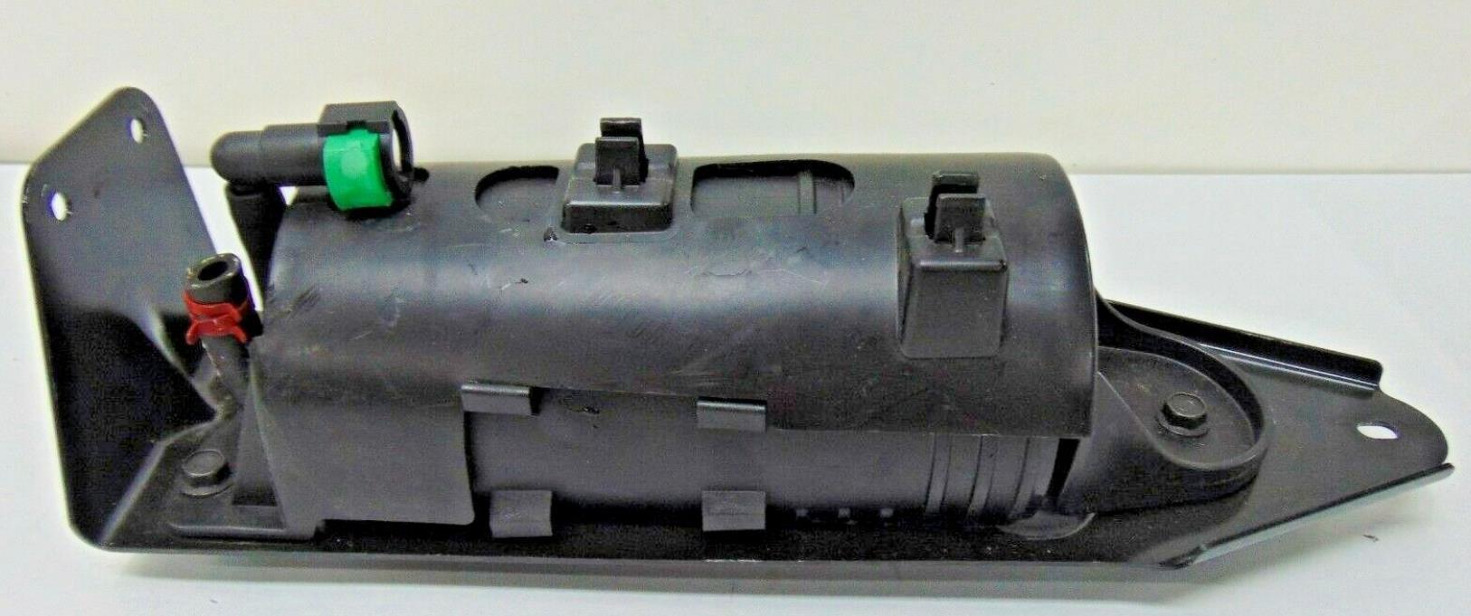
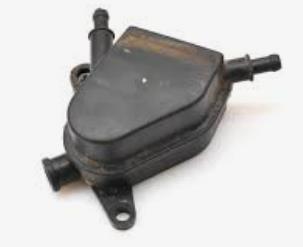
- The system usually consists of a charcoal canister, some valves, hoses and vents, in the fuel storage and handling system, fuel cap, and sometimes a carbon element in the air induction system.
- When fuel evaporates inside your tank, the vapors are transferred to the Evaporative Emission Canister which is filled with activated carbon (charcoal). The fuel vapor is stored until it can be burned in the engine with the normal air fuel mixture.
- At the appropriate conditions, a valve creates vacuum and “purges” vapors from the canister. Fresh air is drawn in through canister vents and the gasoline vapors are drawn from the canister and delivered to the engine.
- Gasoline vapors displaced when an empty tank is refilled (refueling emissions) are also controlled by the evaporative emission control system.
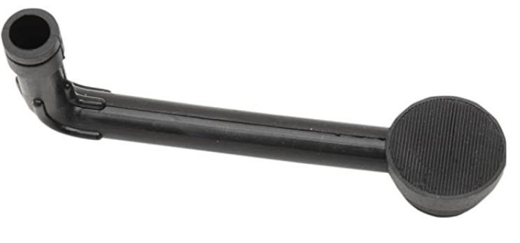
- Ensuring a good fitting and functioning gas cap is key to helping control evaporative emissions.
PCV – Positive Crankcase Ventilation
- When an engine is operating, some of the air and fuel mixture from the combustion chamber gets past the piston rings and into the crankcase. This is called blow-by.
- Blow-by is unavoidable, because rings cannot seal 100% for obvious reasons.
- This blow-by can produce sludge and contamination of your engine oil, due to accumulated oil and fuel vapors clinging to surfaces inside your engine.
- Blow-by gases in the crankcase are routed to the induction system and are burned in the engine instead of being ventilated to the air.
- The PCV system is a valve that operates at idle or low engine speeds.
- At low engine speeds, there is greater vacuum inside the manifold (lower air pressure) which allows the system to suck the gases from the crankcase into the intake manifold for another shot at combustion.
- When the engine speeds up, air pressure rises and thus reduces the amount of PCV that can be sucked in. The pintle is tapered to close as less vacuum is available, preventing PCV from happening in those conditions. This is good because too much oil vapor has a negative effect on fuel octane and reduces engine performance.
How Does This Apply to Dynojet and our Products
Power Commander
- Interfaces with the vehicle’s ECU or fuel injectors directly or indirectly. The primary purpose of this product is to alter the fuel delivery to change the air-fuel ratio.
Power Vision
- Interfaces with the vehicle’s ECU and alters the calibration. The calibration contains instructions that alter the behavior or output of stuff like fuel injectors, spark advance timing, electronics throttle control, and many other things.

Since these products interface directly or indirectly with the vehicle’s emission control system and can alter “elements of design”, they are required to demonstrate compliance with federal or CA mobile source emission regulations.
Potential Emissions Impacts of Tuning
Key Parameters that may impact vehicle emissions
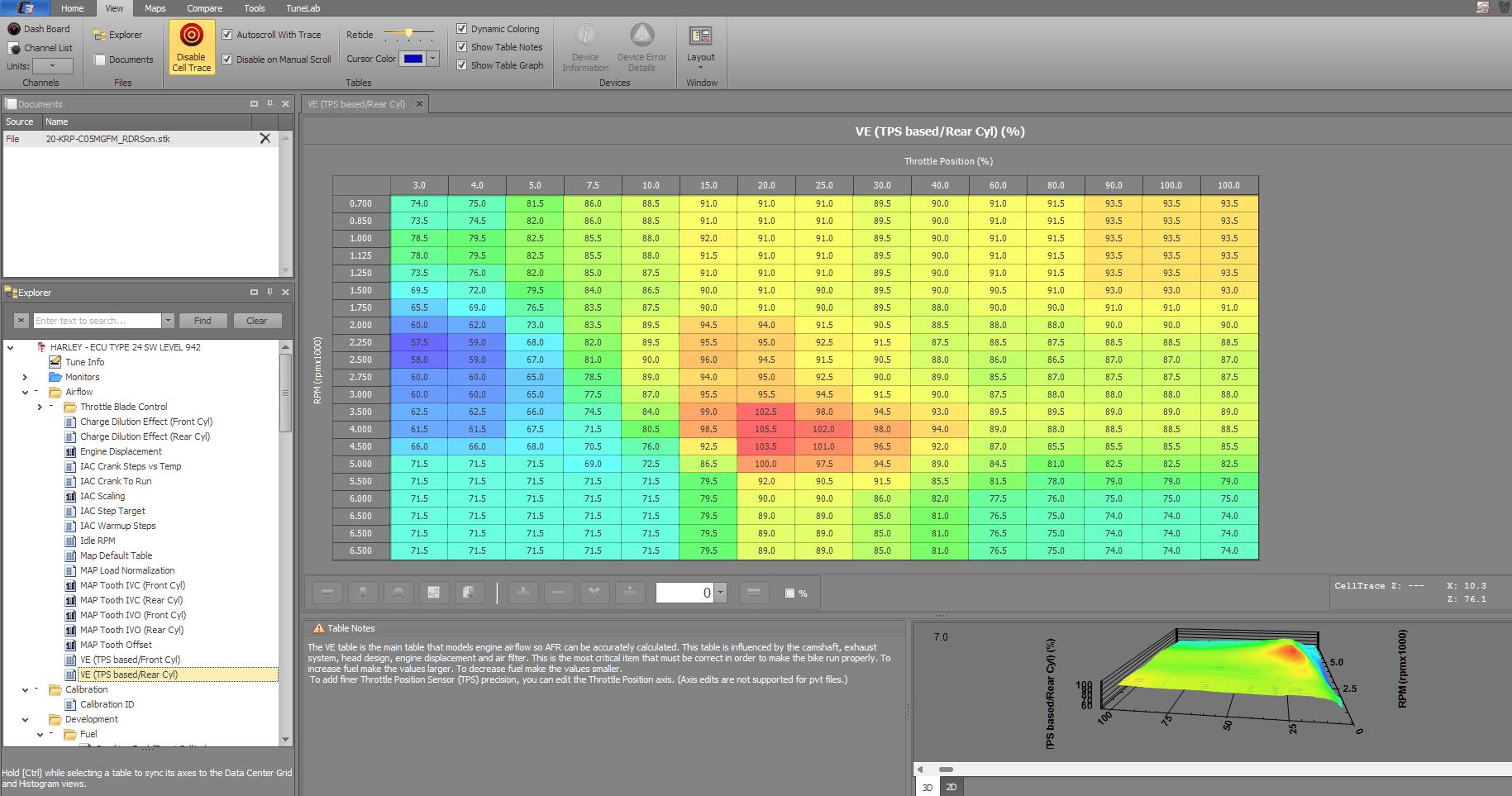
- VE Tables & MAP
- Fuel rail pressure & pulse width
- Fuel injection timing
- Open Loop Fueling
- EGR related parameters
- Ignition timing
How Does This Apply to Dynojet and our Products
VE Tables & MAP Load
- The MAP sensor is one of the primary sensors used for all engine controls including fueling as well as ignition timing and torque calculations.
- Changes to the air intake, air filter, cam, exhaust, or other modifications that can alter the ability of the engine to ingest air and expel exhaust intake related changes will usually require changes to the VE tables.
- On vehicles with narrowband O2 sensors, changes to the VE table outside of the closed loop operation area will impact fueling that the ECU can’t correct for.
- Since fuel trim values are usually for a range of loads, errors in one area of a VE table function may not be properly accounted for by fuel trim values resulting in incorrect fuel trims as load/airflow changes.
- Incorrect VE table values can result in incorrect fueling and other calibration errors that could result in increased emissions.
Fuel Injection Timing
- Changing the time at which the inject opens relative to engine position can have a significant impact on emissions
- When aftermarket cams are used that alter when the intake and exhaust valves open and close require calibration changes
- Allowing fuel to puddle on the back of a closed valve (to early) or entering the combustion chamber when the valve is already open (too late) can have a significant impact on emissions
Open Loop Fueling
- 3 way catalytic converters are designed to operate at lambda 1 for optimal emissions reductions.
- Changes to the load value controlling when the system commands an AFR other than lambda could result in increased emissions and reduced fuel economy.
- The vehicle should remain in closed loop fuel control under most normal driving conditions.
- Changes to the target AFR value when enrichment/WOT fueling is active can also increase emissions and impact fuel economy.
- Note that fuel enrichment strategies exist to protect engine components including emissions related components like catalytic converters and O2 sensors. Changes to these protection strategies can impact the durability of these components resulting in premature component failure.
EGR Related Parameters
- Exhaust Gas Recirculation (EGR) is used in gasoline (spark ignition) engines to reduce NOx emissions
- EGR reduces combustion temperatures, reducing NOx emissions
- EGR valves are used to route exhaust gas into the engine
- EGR valves are not commonly used in powersports vehicles, but there are systems and control techniques in use that ultimately impact the amount of EGR introduced into the combustion process
- In addition to being used for maximizing engine power, camshaft position can be used to generate internal EGR (no external EGR valve needed) so changes in camshaft timing, especially under light load and cruising
conditions, can impact emissions and fuel economy.- Changing camshaft position can also impact knock sensitivity since EGR tends to reduce knock sensitivity.
Ignition Timing
- Ignition timing impacts combustion efficiency so changes to ignition timing may impact vehicle emissions.
- Higher spark advance tends to reduce exhaust gas temperatures while lower spark (less advance) tends to increase exhaust gas temperatures
- Ignition timing is often used to help achieve desired catalyst temperature, especially during cold start conditions, in order to improve catalyst performance and reduce vehicle emissions.
- Changes to the spark advance, especially during warm up and light load/cruising operation, may impact catalytic converter operating temperatures which may impact emissions.